HomeThe Bridge360° TourHistoryWalk & CyclePlan Your VisitWhat’s NearbyAccommodation

Engineering the crossing

An accessible look at the timber viaduct, steel spans, railway, estuary conditions and the engineering that has kept Pont Abermaw in use.

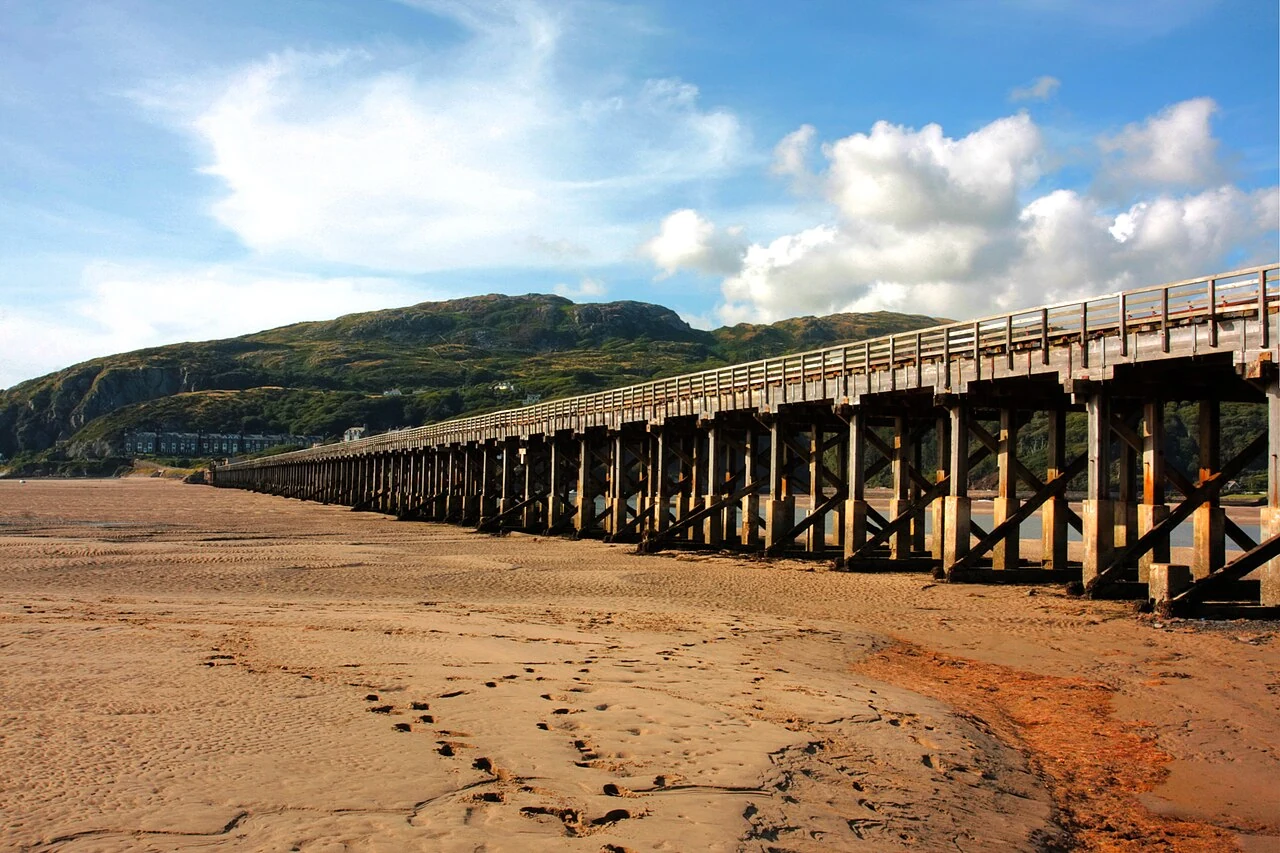
Barmouth’s timber section at low tide · photograph from the site archive
How it works

Timber, tides, track and steel

Six facts about the crossing. Photographs show the actual bridge; diagrams explain general or historical principles.

General timber viaduct diagram
Diagram: repeated supports

Why timber?

Timber construction allowed a long, low crossing supported by repeated frames. Network Rail specified sustainably sourced hardwood for the modern timber renewal.

Barmouth’s timber section at low tide
Photo: timber spans

113 original timber spans

Barmouth Town Council records 113 wooden spans and eight iron spans in the original structure.

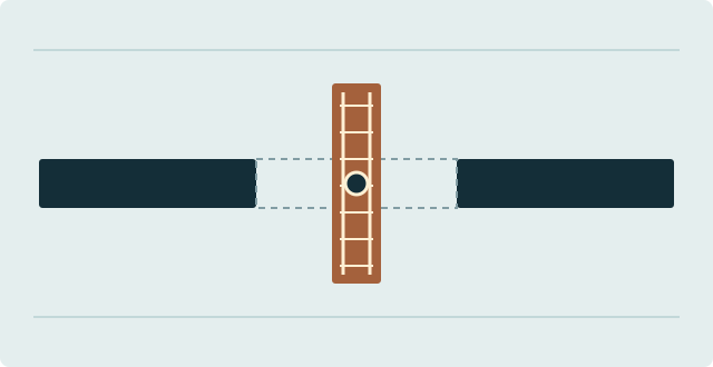
Simplified historical swing model
Historical swing principle

The rebuilt steel section

Cadw records rebuilding in stages from 1899 to 1909. Its structural description identifies a five-span steel section at the Barmouth end.

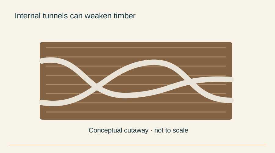
Diagram of tunnels inside timber; not a record of actual bridge damage
General damage diagram

Teredo

Teredo damage was discovered in bridge timbers in 1980, prompting extensive repairs. These marine borers, also called shipworms, are molluscs.

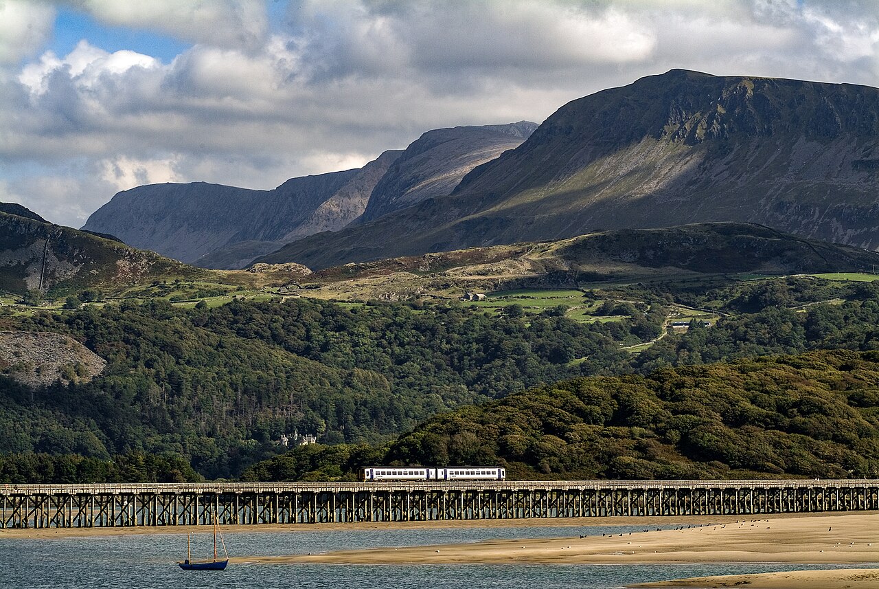
A train crossing Barmouth Bridge
Photo: railway crossing

A working railway

The structure still carries the Cambrian Coast railway while pedestrians and cyclists use the adjacent walkway.

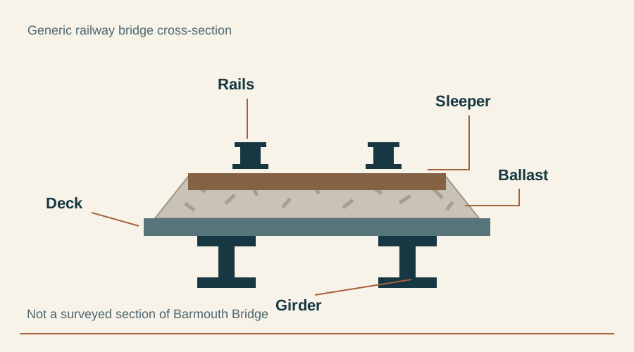
Generic railway bridge cross-section
Generic track layers

Modern restoration

The restoration finished in December 2023. Its final phase included two new metallic spans weighing 160 tonnes each, plus track and walkway renewal.

Facts checked 14 October 2026: Barmouth Town Council’s bridge history · Cadw’s listed-building record · Network Rail’s completed restoration · Network Rail restoration FAQ (PDF) · Natural History Museum: wood-boring molluscs.

Reading the structure

What to look for at the crossing

Follow the labels to see how the parts work together. These diagrams explain general engineering principles; they are not measured drawings of the bridge.

A deck, spans and trestles

The deck is the platform carrying the railway. A span is the length of deck between neighbouring supports; the supporting frameworks are trestles. In a timber viaduct, many short spans together cross a wide gap. This is why the view from the shore tells you more about the structure than the view along the walkway.
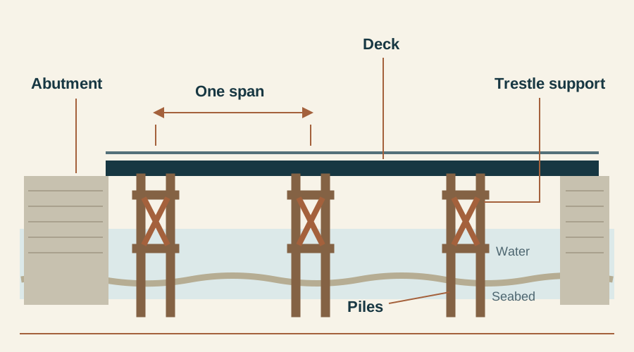
Deck, spans, trestle supports, abutment and piles in a simplified side elevation.
Side elevation · simplified timber viaduct, not to scale. Tap the diagram to enlarge.

Why diagonal members matter

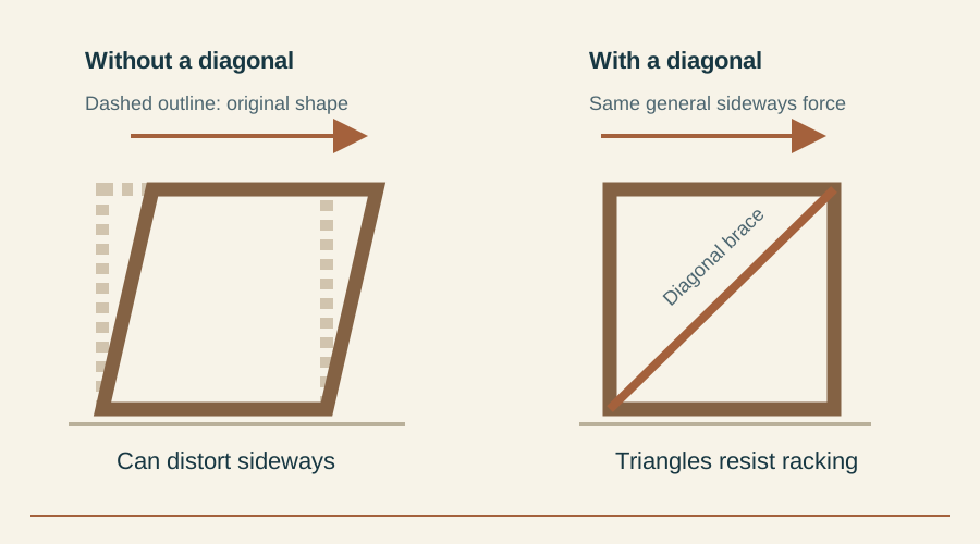
A rectangular frame can distort sideways. Diagonal bracing divides it into triangles, making it more resistant to changing shape. On Barmouth Bridge, look for the diagonals between the timber supports and the contrast with the metal framework at the northern end. The diagonals brace the structure against sideways distortion.

Unbraced and diagonally braced frames compared under a sideways force.
General engineering principle · bracing helps a frame resist sideways distortion. Tap the diagram to enlarge.

Railway and shipping, in one crossing

The original northern opening used a “cock and draw” mechanism to make a passage for vessels. The later swing span turned horizontally around a central pivot instead.

The bridge does not swing today. Network Rail states that the renewed bridge is non-operational as a swing bridge, with its key mechanisms retained to preserve its heritage.

Use the buttons to explore the historical principle, not present-day operation.

Town Council history · Network Rail’s explanation (PDF, question 4)

Historical model: span closedCentral pivot · plan view
Fixed sectionsRotating span

Simplified historical model; not to scale. The vessel route is beside the central pivot.

A small glossary

Pile
A long foundation member that transfers load into the ground beneath the water.
Abutment
The support at the end of a bridge, where the crossing meets the land.
Girder
A major horizontal member carrying loads across a span.
Ballast
The stone beneath and around railway sleepers, supporting and stabilising the track.
Generic railway bridge cross-section labelling rails, a sleeper, ballast, deck and girder.
Generic track cross-section · not a surveyed section of Barmouth Bridge. Piles and the abutment are labelled in the first diagram. Tap the diagram to enlarge.

For the bridge’s recorded arrangement, see Cadw’s structural description. It records 113 groups of timber supports; support groups should not be confused with the original span count quoted above. General diagrams omit details such as raking shores, foundation works and the separate walkway.

Keep exploring

The Bridge GuideExplore in 360°Plan Your VisitWhat’s Nearby